Looking good, Matt. When do you hope to give it it's maiden voyage?

My Electric Brewery Build
#101

Posted 01 February 2014 - 09:07 AM
#102

Posted 01 February 2014 - 09:59 AM
Looking good, Matt. When do you hope to give it it's maiden voyage?
Hopefully April sometime.
#103

Posted 20 March 2014 - 03:44 PM
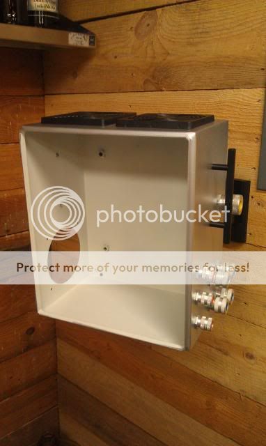
Well I've had quite a few set backs this year on the progress of the build. But I have done a few things recently. I got some free enclosures for the control panel from my old job. The only problem was there was a large hole cut-out on the door panel. That is why I have used a piece of plastic on the front door to fill the hole.
I mounted the control panel on a wall tv mount. It basically sat in this state for the last few months until today I took it down to start wiring.
What type of mount did you use. I haven't even began wiring and the thing is pretty heavy as it is!
#104

Posted 21 March 2014 - 07:15 AM
#105

Posted 21 March 2014 - 07:43 AM
For another approach, I just lagged my box to wall studs. Granted, i did not want my panel to move seeing it had 3 conduits attached to the box.
httpss://lh4.googleusercontent.com/-Wa751wScBZg/UyxP9O2vhtI/AAAAAAAAEec/3u9kxegVjIY/s640/panel.jpg
#106

Posted 21 March 2014 - 08:23 AM
For another approach, I just lagged my box to wall studs. Granted, i did not want my panel to move seeing it had 3 conduits attached to the box.
httpss://lh4.googleusercontent.com/-Wa751wScBZg/UyxP9O2vhtI/AAAAAAAAEec/3u9kxegVjIY/s640/panel.jpg
Interested in your venting system, what is the fan that drives it? The green thing? Has it been effective for you? Is it loud?
I am envisioning a single vessel electric BIAB system with a 240v/3500w portable induction cooktop and an 11 gallon kettle. I would badly need the venting though.
Edited by ettels4, 21 March 2014 - 08:27 AM.
#107

Posted 21 March 2014 - 08:30 AM
Interested in your venting system, what is the fan that drives it? The green thing? Has it been effective for you?
it is an inline 6" vortex fan. I got it off amazon and it has worked fine for my. I did not bother to build a hood because the MLT never get to the point where steam is an issue so I just wanted it over the BK. the only time I have issues is in the winter when it is cold out. I have to leave the fan on for a bit for all teh condensation built up to dissipate or else it will come down the pipe. I have a "gutter" made out of copper pipe on the bottom of the flat part that directs any water into my sump. As of now I have no plans to make any changes to the exhaust set up.
#108

Posted 21 March 2014 - 08:44 AM
#109

Posted 21 March 2014 - 09:22 AM
I can't mount to the wall since mine are concrete. I really don't want to mess with concrete fittings. I do have a old stand which the base is an upside down disk from a disk farm implement. There is about a 5ft tall pipe welded to the center of the disk. I'm thinking of trying to come up with a way to attach the panel to the pipe with some type of mount.
Concrete would not stop me and that was the original plan but the layout did not work. I can see not wanting to mess with it though.
Why not use 2 flanges, and elbow and tee and come up from the base have the tee and one flange at teh bottom and the elbow and other flange at the top and bolt the box to the flanges? I am sure an MS paint drawing would help here.
#110

Posted 21 March 2014 - 09:26 PM
Why let concrete stop you when you have tapcons a available to you?I can't mount to the wall since mine are concrete. I really don't want to mess with concrete fittings. I do have a old stand which the base is an upside down disk from a disk farm implement. There is about a 5ft tall pipe welded to the center of the disk. I'm thinking of trying to come up with a way to attach the panel to the pipe with some type of mount.
#111

Posted 22 March 2014 - 06:24 AM
Why let concrete stop you when you have tapcons a available to you?
I know this. And it would be fairly easy to do. I guess I should of mentioned I wouldn't mind having the panel closer to the outside edge of the table the vessels are on so I don't have to reach back to the panel all the time. Make sense?
Matt has a nice mount that pulls the panel away from the wall. So depending on how much something like that costs I will consider using tapcons to the mount.
#112

Posted 24 March 2014 - 07:05 AM
Looking at the back of your push button LED switches you have an extra NO contact block. The same LED push buttons I have for my pumps came with one set of contact blocks. I know you used all of these type of switches in your application but I'm wondering why you are using two sets of contact blocks on your switches?
Edited by BlKtRe, 24 March 2014 - 07:06 AM.
#113

Posted 24 March 2014 - 09:35 AM
Looking at the back of your push button LED switches you have an extra NO contact block. The same LED push buttons I have for my pumps came with one set of contact blocks. I know you used all of these type of switches in your application but I'm wondering why you are using two sets of contact blocks on your switches?
Because otherwise the LED would not come on when pushed because I am using them for the timer/alarm feature on/off. So there is no power running through them until the alarm goes off. I added the second NO contact to run the power through for the LED of the switch. I didn't put them on the switches for my pumps, so if that's the only two places you plan on using those switches you won't need extra blocks.
#114

Posted 24 March 2014 - 11:04 AM
Gotcha. My alarms will be going through the paddle switches for the PIDs. Wasn't planning alarms for the pumps.
#117

Posted 24 March 2014 - 07:30 PM
Here is a link to the hardware parts of it. Link
The Neutrik parts I know you already saw posted in Blktre's thread. I took out the strain relief that comes with the element housing and had to open it up a little to get the Neutrik panel mount to fit inside. But after that everything else should be self explanatory.
#118

Posted 24 March 2014 - 08:58 PM
That is really nice. I don't think anybody knows about the Neutrik power connections that are building in the electric community. Only place I've seen them is thru you Matt and they are nice!
My only problem was cutting a hole for the 32amp panel mount. The female in your pic. The sizing is difficult. How did you cut SS for that part?
#119

Posted 25 March 2014 - 02:52 AM
#120

Posted 25 March 2014 - 03:32 AM
I used a large step bit. The SS housing already had a fairly large hole for the strain relief. I just opened it up a couple of sizes, maybe to 1" or so? I can't remember would have to check when I get home.That is really nice. I don't think anybody knows about the Neutrik power connections that are building in the electric community. Only place I've seen them is thru you Matt and they are nice! My only problem was cutting a hole for the 32amp panel mount. The female in your pic. The sizing is difficult. How did you cut SS for that part?
1 user(s) are reading this topic
0 members, 1 guests, 0 anonymous users


