
The PID/Solenoid/Switch still section is not correct. If you build it as shown, when the PID tries to energize the solenoid, it will short out your 120 VAC trunk lines.When I can get to a computer where I can draw a what I am tlaking about, I will show you what I mean.zymotyou're right ... thanks! I was attempting to make everything fit and must of missed that. v. 2.0.2


Does this wiring diagram look like it would work
Started by
EWW
, May 22 2010 12:53 PM
31 replies to this topic
#21

zymot
-

- Patron
-

- 25637 posts
Comptroller of Small Amounts of Money
- LocationMortville
Posted 24 May 2010 - 11:01 PM
#22
Stout_fan
-

- Patron
-
- 3115 posts
Frequent Member
- LocationKnoxville, TN
Posted 25 May 2010 - 08:16 AM
I don't think this was mentioned. But other than the mains disconnect, you only need to switch one leg of the loads.SPST switches are a lot cheaper than DPST ones.
#23
zymot
-
- Patron
-
- 25637 posts
Comptroller of Small Amounts of Money
- LocationMortville
Posted 25 May 2010 - 12:03 PM
Good point. the SPST switches are cheaper. The DPST have a hypothetical added safety margin of not putting 120 VAC down all around the rig, except when the device is energized.I don't think this was mentioned. But other than the mains disconnect, you only need to switch one leg of the loads.SPST switches are a lot cheaper than DPST ones.
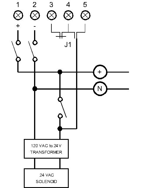
Here is a solution to the problem I mentioned above.This assumes that the PID is configured such that when the temp condition is met, the PID switches the HOT leg of your trunk to terminal 3 thru 5. In other words, I assume your wiring of terminals 1-5 is correct and safe.The PID/Solenoid/Switch still section is not correct. If you build it as shown, when the PID tries to energize the solenoid, it will short out your 120 VAC trunk lines.When I can get to a computer where I can draw a what I am tlaking about, I will show you what I mean.zymot
Edited by zymot, 25 May 2010 - 12:05 PM.
#24
EWW
-

- Patron
-
- 26193 posts
Regular, normal human being
- LocationSomewhere special
Posted 25 May 2010 - 01:40 PM
Zymot you deserve a few bottles of the first batch I do on this when I finish it...big thanks! My wiring on the PID is based off how I saw it wired elsewhere on the web - I plan to double check that when I get the device and manual in the mail.The only other thing I haven't figured out is how to effectively ground to the GFCI. For some reason I just can't visualize this without the pieces in front of me ... Any thoughts?Good point. the SPST switches are cheaper. The DPST have a hypothetical added safety margin of not putting 120 VAC down all around the rig, except when the device is energized. Here is a solution to the problem I mentioned above.This assumes that the PID is configured such that when the temp condition is met, the PID switches the HOT leg of your trunk to terminal 3 thru 5. In other words, I assume your wiring of terminals 1-5 is correct and safe.
#25
EWW
-
- Patron
-
- 26193 posts
Regular, normal human being
- LocationSomewhere special
Posted 25 May 2010 - 01:43 PM
Zymot you deserve a few bottles of the first batch I do on this when I finish it...big thanks! My wiring on the PID is based off how I saw it wired elsewhere on the web - I plan to double check that when I get the device and manual in the mail.The only other thing I haven't figured out is how to effectively ground to the GFCI. For some reason I just can't visualize this without the pieces in front of me ... Any thoughts?Good point. the SPST switches are cheaper. The DPST have a hypothetical added safety margin of not putting 120 VAC down all around the rig, except when the device is energized. Here is a solution to the problem I mentioned above.This assumes that the PID is configured such that when the temp condition is met, the PID switches the HOT leg of your trunk to terminal 3 thru 5. In other words, I assume your wiring of terminals 1-5 is correct and safe.
#26
zymot
-
- Patron
-
- 25637 posts
Comptroller of Small Amounts of Money
- LocationMortville
Posted 25 May 2010 - 02:44 PM
Homebrewers help other homebrewers. It is the most altrusistic hobby I know of.Zymot you deserve a few bottles of the first batch I do on this when I finish it...big thanks! My wiring on the PID is based off how I saw it wired elsewhere on the web - I plan to double check that when I get the device and manual in the mail.
A simplified description.The job of a GFI is to measure the current going out of the + leg and compare it to the amount of current that gets returned on the N leg. If more current goes out than comes back, the GFI assumes the missing current is going through your body and shuts everything down.So if you are going to use the GFI, leaving the ground open will give you the safety factor of a GFI.If your pump, switches, solenoids and transformers have any current leakage, it will trip the GFI and could become quite annoying.If you want to, you could ground the frame of your sculpture frame & brew pots. See if the other solenoids, pump etc cause the GFI to trip.zymotThe only other thing I haven't figured out is how to effectively ground to the GFCI. For some reason I just can't visualize this without the pieces in front of me ... Any thoughts?
#27
Stout_fan
-
- Patron
-
- 3115 posts
Frequent Member
- LocationKnoxville, TN
Posted 26 May 2010 - 05:25 AM
That's why you put the switch on the hot side and not the neutral.And of course, that presumes your 120v outlet has been wired properly.And there is not too much neutral lift.... The DPST have a hypothetical added safety margin of not putting 120 VAC down all around the rig, except when the device is energized. ...
#28
zymot
-
- Patron
-
- 25637 posts
Comptroller of Small Amounts of Money
- LocationMortville
Posted 26 May 2010 - 10:17 AM
I guess my qualifier of hypothetical wasn't good enough for you? (J/K)When you are talking an environment that will have a large quantity of liquids and manual switches and PID switches opening and closing automatically and metal frames and stuff and sparks and solenoids, switching both legs of the AC isn't a bad idea. Other than your previously noted financial impacts.zymotThat's why you put the switch on the hot side and not the neutral.And of course, that presumes your 120v outlet has been wired properly.And there is not too much neutral lift.
#29
EWW
-
- Patron
-
- 26193 posts
Regular, normal human being
- LocationSomewhere special
Posted 26 May 2010 - 11:02 AM
Both good points on the switches ... We're not talking about huge money here. Sure the DPST are twice as much, but they are still under $5. SPST are around $2. With that being said, I may just go with SPST mini toggles for everything except the main power switch to help keep the size of my control panel more compact.
#30
3rd party JKor
-

- Patron
-
- 64137 posts
Puller of Meats
- LocationNW of Boston
Posted 26 May 2010 - 01:14 PM
MaybeI'm misunderstanding zymots diagram, or the terminal functions, but I don't think the drawing in zymots post will work. My uinderstanding of the controller is that it has an internal relay that switches the hot leg of the 120VAC circuit. You should have the hot leg going into the controller on terminal 5 and going out on terminal 4. I don't understand why terminal 3 is jumped to terminal 4 unless terminal 3 is at line voltage, then my point is moot. Although, if that is the case, I don't see the point of the SPST switch between the hot leg going into terminal 1 and hot leg coming off terminal 5, unless it is a manual bypass switch?
#31
zymot
-
- Patron
-
- 25637 posts
Comptroller of Small Amounts of Money
- LocationMortville
Posted 26 May 2010 - 01:47 PM
You make a good point. In my comments that came with my diagram, I had the caveat of:MaybeI'm misunderstanding zymots diagram, or the terminal functions, but I don't think the drawing in zymots post will work. My uinderstanding of the controller is that it has an internal relay that switches the hot leg of the 120VAC circuit. You should have the hot leg going into the controller on terminal 5 and going out on terminal 4. I don't understand why terminal 3 is jumped to terminal 4 unless terminal 3 is at line voltage, then my point is moot. Although, if that is the case, I don't see the point of the SPST switch between the hot leg going into terminal 1 and hot leg coming off terminal 5, unless it is a manual bypass switch?
The PID terminals 1 thru 5 in my drawing are exactly as EWW has shown them in every one of his diagrams. (Term #1 = Hot, Term #2 = Neutral, Term 3 thru 5 bussed? = switched hot output)I did not dig through an owner's manual to confirm this portion of the design.zymotThis assumes that the PID is configured such that when the temp condition is met, the PID switches the HOT leg of your trunk to terminal 3 thru 5. In other words, I assume your wiring of terminals 1-5 is correct and safe.
#32
Stout_fan
-
- Patron
-
- 3115 posts
Frequent Member
- LocationKnoxville, TN
Posted 27 May 2010 - 05:47 AM
Well, only hypothetically.I guess my qualifier of hypothetical wasn't good enough for you? (J/K) ...zymot

0 user(s) are reading this topic
0 members, 0 guests, 0 anonymous users

