

I have been working on my own automated brewing system.I have pretty much finalized hardware design. It has some elements I have not seen in other homebrewing system. All the hooks are in place to automate the system using the micro-controller of your choice. I went with a Raspberry Pi because I want to serve up web pages for control and display status.Here is the design history.It is a propane based system. Maybe someday I will go electric as the system can work on a electric brewing system quite nicely. For now, I am comfortable with propane.I started off with a HERMS controlled PID. The PID temp probe looks at the output of the mas tun. Wort out of the pump hits a tee connection. Each side of the tee has a 12V DC solenoid valve. The PID alternates, opens one valve, closes the other. One valve passes wort through the HERMS coil back into the mash tun. The other valve returns the wort directly to the mash tun, bypassing the HERMS coil. The PID alternates between HERMS and bypass. The PID goes into a control box.Simple enough.I did not want to plug and unplug pump(s) to turn them on and off. Switched 120V AC GFI sockets are in order. My brew area is in flux, I am not sure where my brew pots will go and where the control box would go. I decided to make a second box with 120V AC input & 3 ea switched AC outlets. AC goes on and off via relays in the AC box. An umbilical cable between the control box and the AC box turns each socket on and off. Relays and a control cable. Easy, I can do that.I added a propane manifold and a propane solenoid valve + plus a spark electrode to ignite fire each burner. (I got two burners) Next, add a PID bypass switch and open/close the HERMS solenoid valves manually. Makes sense. Lastly I added a couple auxiliary 12 VDC outputs that I can switch, for future use(s).I decided move the switches off the front of the control box. Make a small control panel with buttons connected by a cable to the control box. Why? Maximum design flexibility and (to be honest) a bit of the "Wow! That’s cool†factor.Next piece of the puzzle was monitoring temps. I wanted to monitor HLT, Boil Kettle, output of wort chiller temps. That was 2 more PIDs, at least. I discovered the Raspberry Pi can read temp probes and you can display the temps via an HTML page. A Raspberry Pi was added to the design. They are $40, cheaper than 2-3 PIDS. Plus they come with GPIO. I have a second way to turn stuff on and off.To this point, I have a control panel with following buttons:1 ea master On/Off system switch (hit off and everything goes into safe mode)2 ea propane burner On/Off + spark generator for each burner3 ea 120V AC GFI Sockets On/Off1 ea PID/Manual mode switch1 ea MT -> HERMS solenoid valve open/close1 ea MT -> HERMs bypass solenoid valve open/close2 ea 12V DC NO/NC Aux outputsAll of these On/Off functions are duplicated by the Raspberry Pi. The RPi and push switches can be mixed and matched. E.g. The RPi can turn On AC socket #1, the control panel can turn off AC socket #1.The control signal is very low current and low voltage. You can use any box you like and use any normally open momentary push switches. You can build the box that houses the equipment with what you like.Soon I will post the design in electronic cookbook format. Maybe there is some ideas you can add to your system.

2 replies to this topic
#1

zymot
-

- Patron
-

- 25589 posts
Comptroller of Small Amounts of Money
- LocationMortville
Posted 01 May 2015 - 01:19 PM
#2
zymot
-
- Patron
-
- 25589 posts
Comptroller of Small Amounts of Money
- LocationMortville
Posted 02 May 2015 - 08:32 PM
Here is an update of my brewery design.Figure 1A voltage source, a normally closed push switch, normally open push switch, a DPDT relay coil and contacts. The relay contacts will open and close as you push the NO switch. The NC switch does not do much in this figure. 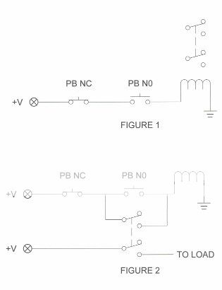 Figure 2We move the relay contacts and put one set of contacts in parallel with the NO switch. When you push the NO switch, the relay engages, the contacts close, one seals around the NO switch. When you release the NO button, the relay stays engaged and the other switch contacts are closed. Push the NC switch when relay is latched, the coil de-energizes, the latch contacts open up and the switch is now open.This is the basic circuit. One button for on, one button off, you have a nifty SPDT switch. The push buttons carry only the relay coil current, they do not have to be heavy duty. The buttons can also be a physically removed from the relay.Figure 3This is where we see one advantage of the switch. There are 3 On buttons in parallel and 3 Off buttons in series. Pushing any one of the On buttons will latch the relay. Pushing any of the Off buttons will kill he latch. E.g. You can latch the relay with button A and kill the latch by pressing button.
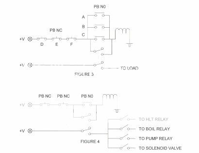 Figure 4Here is an application for your brewery. Put your control devices on the output side of the switch. Put an On and Off button on your control panel, put an Off at the far end of your brewery. If you are in a situation where you want to shut down the brewery pronto, hit the remote Off button and every thing will shut down. You can then reset things as needed, then bring things back up with the On button.Another idea. Make a switch for your boil kettle. Put a Boil Kettle On & Off switch on the control panel, put an On & Off switch near your boil kettle. You can turn on & off your boil kettle while you are close to the kettle.
Figure 2We move the relay contacts and put one set of contacts in parallel with the NO switch. When you push the NO switch, the relay engages, the contacts close, one seals around the NO switch. When you release the NO button, the relay stays engaged and the other switch contacts are closed. Push the NC switch when relay is latched, the coil de-energizes, the latch contacts open up and the switch is now open.This is the basic circuit. One button for on, one button off, you have a nifty SPDT switch. The push buttons carry only the relay coil current, they do not have to be heavy duty. The buttons can also be a physically removed from the relay.Figure 3This is where we see one advantage of the switch. There are 3 On buttons in parallel and 3 Off buttons in series. Pushing any one of the On buttons will latch the relay. Pushing any of the Off buttons will kill he latch. E.g. You can latch the relay with button A and kill the latch by pressing button.Figure 4Here is an application for your brewery. Put your control devices on the output side of the switch. Put an On and Off button on your control panel, put an Off at the far end of your brewery. If you are in a situation where you want to shut down the brewery pronto, hit the remote Off button and every thing will shut down. You can then reset things as needed, then bring things back up with the On button.Another idea. Make a switch for your boil kettle. Put a Boil Kettle On & Off switch on the control panel, put an On & Off switch near your boil kettle. You can turn on & off your boil kettle while you are close to the kettle.
Edited by zymot, 02 May 2015 - 08:32 PM.
#3
zymot
-
- Patron
-
- 25589 posts
Comptroller of Small Amounts of Money
- LocationMortville
Posted 02 May 2015 - 08:45 PM
Figure 5The buttons are replaced by GPIO controlled contacts. The nice thing about this switch is On always = On & Off always = Off. If the switch is already on, closing the On relay will not change anything. Same for the Off relay. If the switch is Off, triggering the Off relay does not change anything. Makes programming easier. You can write a simple "On" script for the On command. Ie. "Engage On GPIO for .5 second". No need for logic such as: "Check if Switch is On. If Off, turn on, if On do nothing."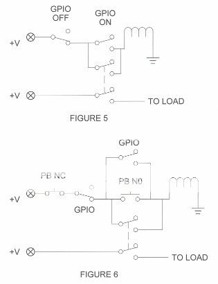 Figure 6This shows a switch with push button and GPIO control design. You can latch the switch with a push button or GPIO and you can open the switch with a push button or GPIO.Figure 7Now we get into some of the details of my design. The relays I have are part of a board made by sainSmart. The board comes with 16 SPDT relays. The relays are a bit different. To get a relay to engage, you pull the "input pin" to ground. The NO (On) push button & NO (On) latch relay contacts work the same. Still place the Off contacts in series with the On switch as shown. You trigger the Off relay contacts by pulling Off relay's trigger to ground. Why did I use up a relay to open the latch? Look at the next figure.
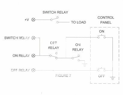 Figure 8The complete push button and GPIO circuit switch, Each GPIO pulls the appropriate relay input pin to ground. Push the On button, the On relay latches and pulls the Switch relay input to ground and the Switch relay closes. Push the Off button, it pulls the Off relay input to ground, the Off contacts open and the switch unlatches.The On GPIO pulls the On relay input to ground, the switch latches. The Off GPIO pulls the Off relay to ground, the Off relay opens and unlatches the switch.
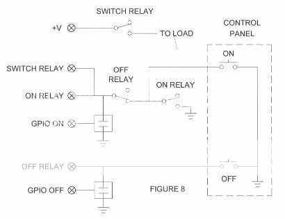
Figure 6This shows a switch with push button and GPIO control design. You can latch the switch with a push button or GPIO and you can open the switch with a push button or GPIO.Figure 7Now we get into some of the details of my design. The relays I have are part of a board made by sainSmart. The board comes with 16 SPDT relays. The relays are a bit different. To get a relay to engage, you pull the "input pin" to ground. The NO (On) push button & NO (On) latch relay contacts work the same. Still place the Off contacts in series with the On switch as shown. You trigger the Off relay contacts by pulling Off relay's trigger to ground. Why did I use up a relay to open the latch? Look at the next figure.Figure 8The complete push button and GPIO circuit switch, Each GPIO pulls the appropriate relay input pin to ground. Push the On button, the On relay latches and pulls the Switch relay input to ground and the Switch relay closes. Push the Off button, it pulls the Off relay input to ground, the Off contacts open and the switch unlatches.The On GPIO pulls the On relay input to ground, the switch latches. The Off GPIO pulls the Off relay to ground, the Off relay opens and unlatches the switch.
Also tagged with one or more of these keywords: DIY
Brewing Forums →
Wine, Mead, & Cider (WM&C) →
Connecticut mead and wine makersStarted by eldernerd , 03 Jun 2013 |
|

|
||
Brewing Forums →
Beer →
My DIY stir plateStarted by SteveMillerTime , 15 Apr 2013 |
|

|
||
Brewing Forums →
Beer →
The Hop Ramp. A filter For Hops and Pellets in Your Brew Kettle.Started by zymot , 12 Apr 2013 |
|
|
||
Brewing Forums →
Beer →
My cheap assed counter pressure bottle filler stand!Started by SteveMillerTime , 23 Mar 2013 |
|

|
||
Brewing Forums →
Beer →
The *official* Brewboy's DIY glycol threadStarted by Genesee Ted , 14 Mar 2013 |
|

|
0 user(s) are reading this topic
0 members, 0 guests, 0 anonymous users

