
 Main components are as follows:Auber Universal 1/16 DIN PID Temperature Controller - linkAuber Liquid tight RTD sensor x 2 - linkAuber multifunction timer, counter, tachometer - link1/4" Solenoid Valve x 3 (for pilots)1/2" Solenoid Valve x 3 (for main burner)Honeywell Q373A2115 Intermittent Pilot Burner Igniter x3 (I'm thinking I will manually fire these with switches - I'm not sure how to wire them to auto fire with the solenoids) I appreciate any guidance on this. I'm designing a 2 tier Brutus inspired system that will fit in my Honda Accord.


Does this wiring diagram look like it would work
Started by
EWW
, May 22 2010 12:53 PM
31 replies to this topic
#1

EWW
-

- Patron
-

- 26167 posts
Regular, normal human being
- LocationSomewhere special
Posted 22 May 2010 - 12:53 PM
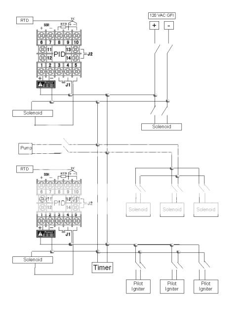
So unfortunately they didn't teach me how to draw a wiring diagram or do complicated wiring in social work school, so I kind of made this up as I went along based on my reading. Does this look like it would work to you electrically smart people?Main components are as follows:Auber Universal 1/16 DIN PID Temperature Controller - linkAuber Liquid tight RTD sensor x 2 - linkAuber multifunction timer, counter, tachometer - link1/4" Solenoid Valve x 3 (for pilots)1/2" Solenoid Valve x 3 (for main burner)Honeywell Q373A2115 Intermittent Pilot Burner Igniter x3 (I'm thinking I will manually fire these with switches - I'm not sure how to wire them to auto fire with the solenoids) I appreciate any guidance on this. I'm designing a 2 tier Brutus inspired system that will fit in my Honda Accord.
Main components are as follows:Auber Universal 1/16 DIN PID Temperature Controller - linkAuber Liquid tight RTD sensor x 2 - linkAuber multifunction timer, counter, tachometer - link1/4" Solenoid Valve x 3 (for pilots)1/2" Solenoid Valve x 3 (for main burner)Honeywell Q373A2115 Intermittent Pilot Burner Igniter x3 (I'm thinking I will manually fire these with switches - I'm not sure how to wire them to auto fire with the solenoids) I appreciate any guidance on this. I'm designing a 2 tier Brutus inspired system that will fit in my Honda Accord.
#2
zymot
-

- Patron
-
- 25583 posts
Comptroller of Small Amounts of Money
- LocationMortville
Posted 22 May 2010 - 01:48 PM
It has been a few years since I specifically worked in the industrial controls business, but non of this makes any sense to me.You have 120 VAC going into something marked + & -. And you 120 VAC basically bussed to all the devices.You have switch symbols that control solenoids. No way to tell what makes the switches open and close. If these are relays, what makes the relays open and close?As drawn, the timer does nothing other sitting on 120 VAC. What do you want the timer to do? It has no ouput.Can provide a simple explanation for whatyou want each sensor to do?Regards,zymot
#3
EWW
-
- Patron
-
- 26167 posts
Regular, normal human being
- LocationSomewhere special
Posted 22 May 2010 - 02:28 PM
Thanks for the reply. I'm no expert, so any help is appreciated.It has been a few years since I specifically worked in the industrial controls business, but non of this makes any sense to me.
All of the devices are 120 VAC, so I assumed that would be the easiest way to get power to them all...is there a better way?You have 120 VAC going into something marked + & -. And you 120 VAC basically bussed to all the devices.
The solenoids are normally closed, and open when power is applied to them (don't they?). I planned to use manual toggle switches to complete the circuit and power the system/open the valve. When the circuit is complete, I'm thinking the PID will act to fire the burners based on the temperature reading of the RTD (the PID has an off/on setting). The PID will act as a relay to do this won't it? I'm I incorrect about this?You have switch symbols that control solenoids. No way to tell what makes the switches open and close. If these are relays, what makes the relays open and close?
This is true, I wanted a built in timer on the control panel to time my mash and hop additions. The only thing it will do is act as a timer, so all it needs is power right? This timer has more capability then my wiring skills, so some of that will be wasted in this application but I'm okay with that.As drawn, the timer does nothing other sitting on 120 VAC. What do you want the timer to do? It has no output.
The temp sensors will trigger the on/off set points of the PID and open close the solenoids connected to it (i think) If I'm off base please let me know. I'm doing the planning before I order the components and want to get this right the first time to prevent costly mistakes. Thanks a lot.Can provide a simple explanation for what you want each sensor to do?
#4
EWW
-
- Patron
-
- 26167 posts
Regular, normal human being
- LocationSomewhere special
Posted 22 May 2010 - 02:44 PM
this is what the system should do if you aren't familiar with it. The addition of the smaller solenoids and electric ignition is so I don't have to reach under the system to light the pilots ... those will be toggle switch controlled in my working diagram.
#5
zymot
-
- Patron
-
- 25583 posts
Comptroller of Small Amounts of Money
- LocationMortville
Posted 22 May 2010 - 03:47 PM
Let me see what I can do to help out here.You have sensors that measure the temp of stuff, like your mash, yoru strike water, your sparge. When the sensor tells the PID you have reached a certain temp, the PID turns one or more things on (or off).Based on what you have drawn, you have power going to all the devices. There are switch symbols to turn the solenoid on and off. What are those switches? Are the switches the toggle switches you talk of? If so, the solenoid opens and closes as you throw the switch the PID will do nothing..What you want to do is have A PID with the temp sensor going into the PID and some sort of control coming out.The control out is typically a DC control voltage out or a switch 120 VAC out. This output(s) go on and off and make the solinoids, and pumps and various other things turn on and off.The timer needs some sort out of input and output, you show nothing like that.Here is a place for you to start.Put 120 VAC into terminals 1 & 2Put your temp sensor into terminals 8, 9 & 10 (details tbd)Here is the tricky part:The various things that get turned on and off come from:Terminals 4 & 5and/orTerminals 13 & 14and/orTerminals 6 & 7These terminals are the various switches. These terminals are what control your solenoids and other devices.How to integrate the timer you show is hard to say.zymot
#6
EWW
-
- Patron
-
- 26167 posts
Regular, normal human being
- LocationSomewhere special
Posted 22 May 2010 - 04:57 PM
Zymot, for some reason I feel like either you aren't understanding what I'm attempting to do or I'm completely missing what you are saying (it's probably me). I think I was confusing both of us with the +/-. The PID can be run on AC or DC (hence the +/-). I initially had this in my diagram to keep lines straight, but since I will be running this off AC it really isn't needed.I went back to my open office diagram to see if I can clear things up because I really appreciate your input. What I am attempting to do is create zones off a main trunk line. I adjusted the colors to attempt to illustrate this. Gray = main power: The switch in the gray oval is my main power control to the board. The gray line is what I'm calling the trunk that I want to run the misc zones off of. I attempted to wire the trunk in parallel to ensure that there is a complete circuit even if a switch or PID turns off/on one of the zones. Redish/Brown is HLT: gas is turned off/on by the PID based on the temp sensorBlue is MLT: works the exact same way as the HLTGreen is BK: gas will be turned off/on via the solenoid that will be powered by a toggle switch on the control panel.Pink is Pilot light controls: each solenoid and igniter will have an independent switch on the control panel. In theory I will flip a toggle to open a solenoid which will turn on a pilot light's gas. Then I will use a different switch to activate that pilot light's electric igniter and light the pilot. Each of the different color boxes inside the pink box indicates a matched pair of pilot gas and pilot igniter.Black is misc controls: The timer will always be powered when the main control panel power is on. This will be used as a count down timer for the mash and hop additions. The pump will have an independent switch on the control panel to turn it off/on. 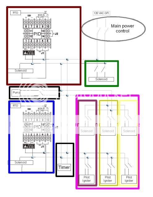 Are you implying that my main power trunk and zone thinking won't work? If so do you have any ideas to make this work?
Are you implying that my main power trunk and zone thinking won't work? If so do you have any ideas to make this work?
#7
zymot
-
- Patron
-
- 25583 posts
Comptroller of Small Amounts of Money
- LocationMortville
Posted 22 May 2010 - 08:56 PM
I think we are on the same page.Your main control power, (grey ellipse)Good idea. The switch cuts off both legs of your 120 VAC. In the case of an emergency, that is what you want to do.After looking at the link for the PID, yes you can operate the PIDs on AC or DC voltage.The sensor into the redish/brown ID.Assuming you get a sensor that is a match to the PID and you program the PID correctly, wired correctly, etc, you are gold.Same comment for the blue PID and temp sensorI now see what you are doing with the redish/brown solenoid. This is the only solenoid that will open and close as a response to the temp sensor on the redish/brown PID.I now see what you are doing with the blue solenoid. This is the only solenoid that will open and close as a response to the temp sensor on the blue PID.All the other switch symbols are panel mounted toggle switches. These devices will accuate as you throw the toggle switch. The green solenoid, black pump, 3x pink solenoids and 3x pink pilot iginiters are manual switch control only.The timer is a display only. Nothing happens automatically when the display reaches 00:00:00If that is what you are looking for, you should be OK.zymot
#8
EWW
-
- Patron
-
- 26167 posts
Regular, normal human being
- LocationSomewhere special
Posted 22 May 2010 - 10:26 PM
Thanks zymot ... I'll be ordering the components in the near future to see if it works in the "real world."EDIT: can you think of any other way that I could wire that timer to make better use of it's abilities?
#9
klickcue
-

- Members
-
- 165 posts
Advanced Member
Posted 23 May 2010 - 04:27 AM
Your pilot igniter will not work as drawn. The spark comes from a high voltage transformer or pilot controller, not 110 VAC.In industrial firing a flame rod, thermocouple or ultraviolet detector would be used to detect pilot flame to allow the main burner control to activate.The pilot device you have listed will supply a standing pilot once gas is applied and the gas is ignited.You could possibly use a gas grill push button piezoelectric device to generate your ignition spark since it is a manned firing device.
#10
3rd party JKor
-

- Patron
-
- 64053 posts
Puller of Meats
- LocationNW of Boston
Posted 23 May 2010 - 06:05 AM
I'll look at it...gimme a few minutes.
#11
3rd party JKor
-
- Patron
-
- 64053 posts
Puller of Meats
- LocationNW of Boston
Posted 23 May 2010 - 06:30 AM
I think what you have will work. I haven't worked with gas, but I'm wondering why you have your pilot gas and pilot ignitors on manual toggles? Do you leave the pilot gas and ignitor on the entire time you brew? Could you wire the pilot gas solenoid, ignitor and main gas line for each zone into one switch/relay so they always come on at the same time?
#12
EWW
-
- Patron
-
- 26167 posts
Regular, normal human being
- LocationSomewhere special
Posted 23 May 2010 - 06:58 AM
Thanks, that will save me a headache I didn't even think about looking into. Per Honeywell it needs 15,000V ... I ain't messing with that. The battery ignition systems from a grill was a backup plan I had in mind so I'll have to see if I can remove the high voltage ignition system and retofit the pilot assembly to hold it.Your pilot igniter will not work as drawn. The spark comes from a high voltage transformer or pilot controller, not 110 VAC.In industrial firing a flame rod, thermocouple or ultraviolet detector would be used to detect pilot flame to allow the main burner control to activate.The pilot device you have listed will supply a standing pilot once gas is applied and the gas is ignited.You could possibly use a gas grill push button piezoelectric device to generate your ignition spark since it is a manned firing device.

 looking at the 2 images it doesn't seem like it will that hard.
 I can't figure out how to do it with 1 switch (without a gas sensor that fires the spark ignition), so I settled on a 2 switch solution. I would like to avoid keeping standing pilots on all 3 burners the whole brew session, but during the mash the pilot will remain lit.I think what you have will work. I haven't worked with gas, but I'm wondering why you have your pilot gas and pilot ignitors on manual toggles? Do you leave the pilot gas and ignitor on the entire time you brew? Could you wire the pilot gas solenoid, ignitor and main gas line for each zone into one switch/relay so they always come on at the same time?
#13
zymot
-
- Patron
-
- 25583 posts
Comptroller of Small Amounts of Money
- LocationMortville
Posted 23 May 2010 - 07:29 AM
It is hard to comment much more without knowing your planned workflow. All I can tell from the diagram you have 2 temp sensors that each one controls it's own solenoid. The solenoids will turn on and off depending on how you have the PID programmed. The other devices are under manual control.For the timer, it has relay outputs that open and close depending on the programming of the timer. You can use those rely to open or close (AKA tun on or turn off) a device based on a time interval(s). Looks as if you can add your own buttons for the Start, Pause, Reset function. I tend to like those over the membrane switch that typically come with these kinds of units. Plus buttons can look cool. You can also use the relay out put to work in combination with some other PID logic or one of your manual switches. Two switches can be wired two ways. Serial or parallel. This is the same serial and parallel you had with light bulbs, think old time Christmas tree lights.Wire 2 switches in serial, you must close both switches to energize a device. This creates a AND logic circuit. E.g. Switch #1 AND Switch #2 must be closed to energize Device X.Wire 2 switches in parallel, you can close either switch to energize the device. This creates an OR logic circuit. E.g. Switch #1 OR Switch #2 can be closed to energize Device X.Off hand I do not know how you might use this, but you got a nice $33.50 (plus shipping and handling) timer, maybe this will help you get some additional function from it.zymotThanks zymot ... I'll be ordering the components in the near future to see if it works in the "real world."EDIT: can you think of any other way that I could wire that timer to make better use of it's abilities?
#14
EWW
-
- Patron
-
- 26167 posts
Regular, normal human being
- LocationSomewhere special
Posted 24 May 2010 - 12:08 PM
I got 6 solenoids given to me from a friend who got them from me from work - they have Viton seals so should be good to go with LP. The three 1/2" solenoids that I would be using on the main burners are 24 VAC and the three 1/4" are 120 VAC. I just got them yesterday and noticed the voltage, so I'll have to rework the wiring to include some transformers. If I use a 120 VAC input / 24 VAC output transformer to step down the power supply for the solenoids do I have to do anything special on the neutral return before it hits the GFCI?
#15
zymot
-
- Patron
-
- 25583 posts
Comptroller of Small Amounts of Money
- LocationMortville
Posted 24 May 2010 - 12:40 PM
The transformer can tap off the 120 VAC, like any other device. This will not affect the GFI, in fact it might lower the likely hood the GFI will trip. You need just 1 transformer for all the 24 VAC solenoids. This assumes the transformer selected has enough current to power 3 solenoids. It should be easy to locate such a transformer, and cheaper too.The switches you have for each solenoid would be on the 24 VAC side of the transformer would switch 24 VAC per each solenoid.I got 6 solenoids given to me from a friend who got them from me from work - they have Viton seals so should be good to go with LP. The three 1/2" solenoids that I would be using on the main burners are 24 VAC and the three 1/4" are 120 VAC. I just got them yesterday and noticed the voltage, so I'll have to rework the wiring to include some transformers. If I use a 120 VAC input / 24 VAC output transformer to step down the power supply for the solenoids do I have to do anything special on the neutral return before it hits the GFCI?
#16
EWW
-
- Patron
-
- 26167 posts
Regular, normal human being
- LocationSomewhere special
Posted 24 May 2010 - 04:48 PM
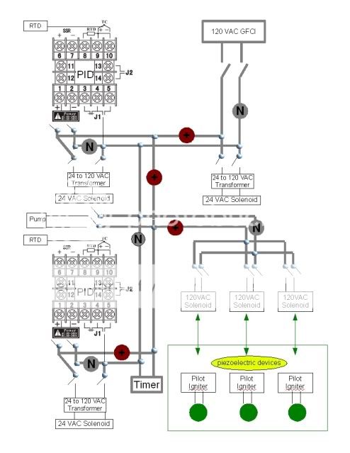
Thanks again. Here's working diagram v. 2.0.1 the bold gray is what I'm calling the trunk line. I added switches going into the PIDs so I would be able to run the burners without the PID if I ever want to. Any all input is greatly appreciated!In other news I picked up $240 worth of steel for the stand today. I should start cutting and welding in a week. Went with cold rolled since I can't weld stainless on my system ... I'll start a construction thread when I get around to starting this.
the bold gray is what I'm calling the trunk line. I added switches going into the PIDs so I would be able to run the burners without the PID if I ever want to. Any all input is greatly appreciated!In other news I picked up $240 worth of steel for the stand today. I should start cutting and welding in a week. Went with cold rolled since I can't weld stainless on my system ... I'll start a construction thread when I get around to starting this.
#17
zymot
-
- Patron
-
- 25583 posts
Comptroller of Small Amounts of Money
- LocationMortville
Posted 24 May 2010 - 05:15 PM
Double check how you have drawn the switches around to the 24 VAC transformer.With the right dot where it is, the both ends of the primary of the transformer will go to the N side of your trunk line. Nothing will happen. When the PID tuen on, short circuit, worse than nothing happens.If you move the right dot to the + side of you trunk line, you fix it so the the switch energizes the solenoid. But then your PID will do nothing. The only way the PID can work is if the switch is closed. If the switch is closed the solenoid is energized and the PID will turn on a previously energized solenoid, no change.Suggested fix. Do not switch the N side of trunk line into transformer. Use one side of the switch and put it in parallel with the PID output. This should create the "OR" typeof logic I think you are looking for.zymotThanks again. Here's working diagram v. 2.0.1
#18
EWW
-
- Patron
-
- 26167 posts
Regular, normal human being
- LocationSomewhere special
Posted 24 May 2010 - 05:47 PM
you're right ... thanks! I was attempting to make everything fit and must of missed that. v. 2.0.2Double check how you have drawn the switches around to the 24 VAC transformer.With the right dot where it is, the both ends of the primary of the transformer will go to the N side of your trunk line. Nothing will happen. When the PID tuen on, short circuit, worse than nothing happens.If you move the right dot to the + side of you trunk line, you fix it so the the switch energizes the solenoid. But then your PID will do nothing. The only way the PID can work is if the switch is closed. If the switch is closed the solenoid is energized and the PID will turn on a previously energized solenoid, no change.Suggested fix. Do not switch the N side of trunk line into transformer. Use one side of the switch and put it in parallel with the PID output. This should create the "OR" typeof logic I think you are looking for.zymot
#19
EWW
-
- Patron
-
- 26167 posts
Regular, normal human being
- LocationSomewhere special
Posted 24 May 2010 - 06:14 PM
I've been thinking about this, and I think I'll just wire in a buzzer to the timer ... everything else seems overly complicated for my application.For the timer, it has relay outputs that open and close depending on the programming of the timer. You can use those rely to open or close (AKA tun on or turn off) a device based on a time interval(s). Looks as if you can add your own buttons for the Start, Pause, Reset function. I tend to like those over the membrane switch that typically come with these kinds of units. Plus buttons can look cool. You can also use the relay out put to work in combination with some other PID logic or one of your manual switches. Two switches can be wired two ways. Serial or parallel. This is the same serial and parallel you had with light bulbs, think old time Christmas tree lights.Wire 2 switches in serial, you must close both switches to energize a device. This creates a AND logic circuit. E.g. Switch #1 AND Switch #2 must be closed to energize Device X.Wire 2 switches in parallel, you can close either switch to energize the device. This creates an OR logic circuit. E.g. Switch #1 OR Switch #2 can be closed to energize Device X.Off hand I do not know how you might use this, but you got a nice $33.50 (plus shipping and handling) timer, maybe this will help you get some additional function from it.zymot
#20
zymot
-
- Patron
-
- 25583 posts
Comptroller of Small Amounts of Money
- LocationMortville
Posted 24 May 2010 - 11:01 PM
The PID/Solenoid/Switch still section is not correct. If you build it as shown, when the PID tries to energize the solenoid, it will short out your 120 VAC trunk lines.When I can get to a computer where I can draw a what I am tlaking about, I will show you what I mean.zymotyou're right ... thanks! I was attempting to make everything fit and must of missed that. v. 2.0.2
0 user(s) are reading this topic
0 members, 0 guests, 0 anonymous users

